
-----BEGIN PGP SIGNED MESSAGE-----
Hash: SHA512
4th Copper Tape Circuit
by Javantea
Dec 3, 2020
Fourth try is a charm. For a while now I’ve been trying to learn how to make cheap and quick copper tape circuits as described briefly in Bunnie’s 2018 Toorcamp Keynote talk where he discusses the elements for electronics development that has so far provided him with much success. Toorcamp in 2018 happened to provide me with the copper tape used in this circuit, so I thought I’d give a shout out to my Neg9 crew and those who shared the weekend with me.
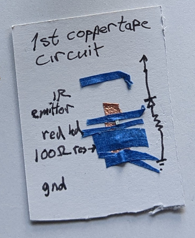
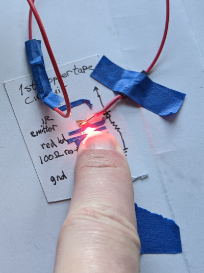
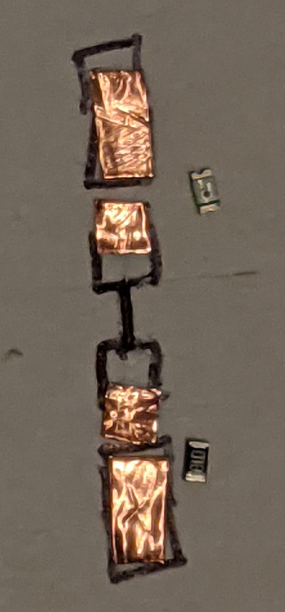
First Copper Tape Circuit
This is the 4th iteration of this circuit. The first circuit used just blue painter’s tape, copper tape, wire, and smd components. I found that the circuit did indeed work, but that it wouldn’t work without pressure on the resistor (which I covered with tape in a futile attempt to get the circuit to be more reliable).
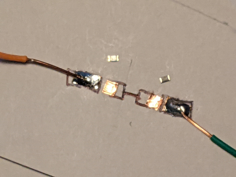
Second Copper Tape Circuit
The second circuit I thought that I could stick the components to blue tape. That didn’t work being so unreliable that I had to hold the card to get it to light. Certainly something was wrong with this idea. I added a small piece of copper tape under the middle of the two components and finally taped it with scotch tape. Neither of those had any beneficial effect unless you want to press hard on the circuit to get it to function. What makes it so that a conductive part lying on a conductive piece of tape doesn’t conduct without some pressure? My guesses are completely speculation, but my belief is firm – without pressure there is a pretty significant gap between two pieces of conductive objects. They don’t just conduct on touch. More speculation: the reason we associate touch with conductivity is because our multimeters only need to touch a conductive object to conduct, but it only conducts because we are putting pressure on the thing we are probing.
Third Copper Tape Circuit
The third circuit I thought that saving money by using CAT5 for the bonding wire and no copper tape. This was a mistake. The LED was easy to solder, it took seconds. You might expect cold joints from a electronics novice. The wires are still securely fastened. The resistor would not solder for anything. So I tried again and again and again until finally I killed a resistor and decided to solder a fresh one to copper tape. It took seconds to solder the resistor to copper tape – just like whenever I solder to a circuit board. It was then that I decided on the correct design for the fourth circuit. I dabbled with the idea of bending the cat5 to become a solderable surface, and that is possible in the future. It doesn’t matter how good I get at it and how cheap the third circuit’s design is – it is bad and I should avoid it.
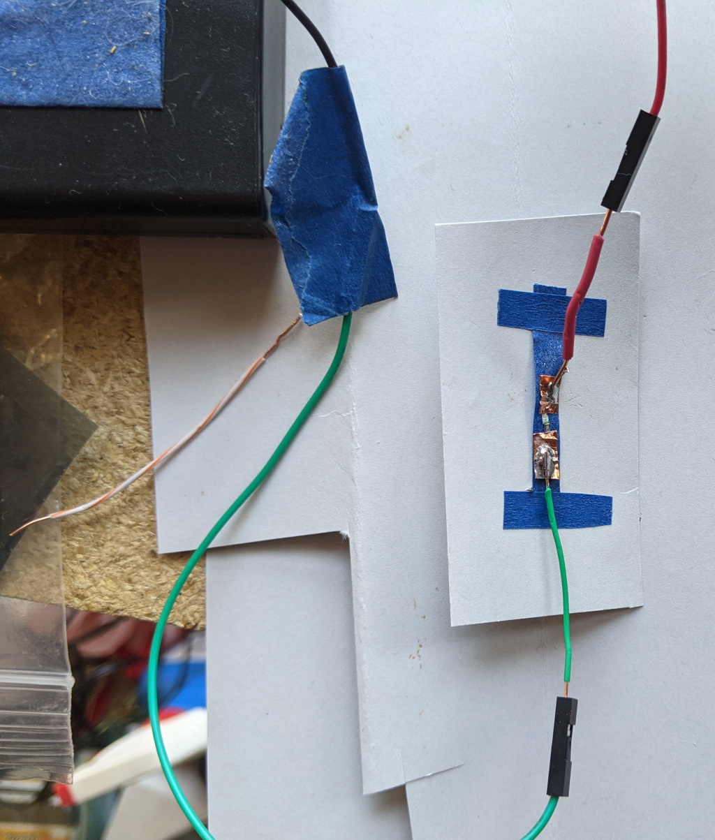
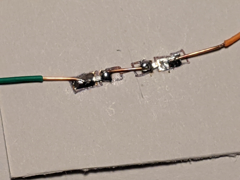
Fourth Copper Tape Circuit
The fourth copper tape circuit was easy to make, easy to solder, and is reliable. It’s components are cheap, quick, good, and it has no drawbacks to the other options. It provides even an excellent option for hackers who have access to circuit board making materials (which I am very close to having), hackers who need a circuit this very minute, engineers who want circuit boards printed at OSH Park, and hobbyists who want circuit boards printed in Hong Kong*. Let’s go through the minutes that it took to create these boards.
* JLCPCB is an incredible circuit board manufacturer and provided me with so many PCBs (for a yet unreleased open source project) that I will have to give away circuit boards for quite a while to get rid of them. They charged $22.44 shipped. That’s right. I can’t compare to OSH Park, but I hear great things.
Step 1
Cut copper tape to the right size. Put copper tape onto a piece of card. You need to put the pads in the right place, but if you get it wrong, you have a few more tries to get it right.
22:36 <@Javantea> mood music Groove Armada - Easy
Step 2
Add solder to the outer pads and solder the outer wires to the copper pad.
Step 3
Solder on the resistor. Use tweezers to hold the resistor where it should be.
Step 4
Solder on the LED.
Step 5
Solder the bare copper wire between the inner copper pads.
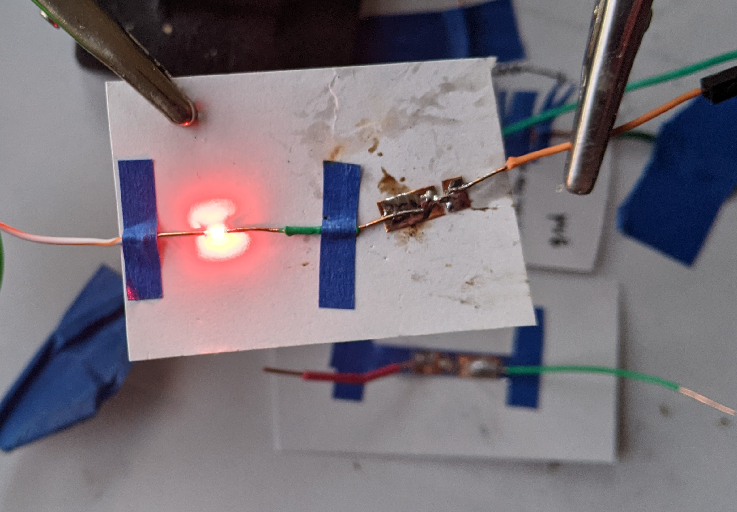
Step 6
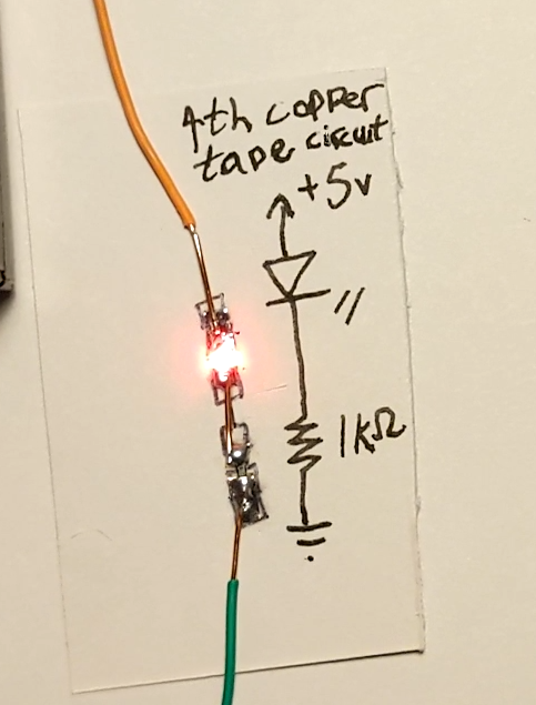
Wire the circuit up to the power source and turn it on.
Step 7
Draw a circuit diagram if you need it. Label the circuit.
Conclusion
We need to find a good project to make with this new technique. My thought is to make a universal remote control for my televisions. I have a Toshiba (don’t laugh) and an LG that uses an external IR only (I’ve never gotten it to work, always used the buttons on the back of the TV). My Sony, Pinnacle (I know), and SSL Labs (¯\_ツ_/¯) remote controls don’t work on them (except that the Toshiba reports that the command is not allowed). So there are actually good Arduino circuits and I have all the necessary components to make a circuit with arduino pro. I can even use female and male headers so that I can remove the arduino pro for use in other circuits (Oscilloscope, Arduino ISP for example) when I’m not switching channels. How many copper pads, how many short cat5 wires will the universal remote take? Probably not a lot. But I will buy a roll of copper tape for the next circuit for sure. Did I mention that copper tape is ridiculously cheap (better stuff is only a little more expensive)? Why would it be ridiculously cheap? Think about a kg of raw copper. Then flatten it to 1mm x 5mm x large number meters. That’s copper tape. How much copper tape did I use for this circuit? 5mm x 8mm x 1mm.

-----BEGIN PGP SIGNATURE-----

iQIzBAEBCgAdFiEEuYE3Yh0wygXiwc1/PGjI28ung+8FAl/J5fcACgkQPGjI28un
g+8Izg/+LiQe0736WGfbTlF+egFBZGMJHSokdxUpgwPAHBn+F6dNN6i4+8fWWuz6
VY7V7vZCZV3PA8aHfmFVn0sWtOdiRJneoux/rjeJyxN/D7f0KfhXKXkeSNhO5Xjv
KqJBj3KACEpdHmqYX/nRj7r98Ujwjr1f6drvEGRcmqhkYfobW7sCKF+PWFyzYpYa
z8XJgYSlaGtPckmZCD2Zj79eEuQ6JJY4T/eTMLemkee+XkpNuU1lJ1gNEnefNWkk
1fiACIMp4D3TQbSgbW1kY5UsqWajtdbS8W9d94U2ozE/akbX1nI7upoIyr0AoR48
5oj+MvfKUSNwXIGlbrLD5lEEGpmF6cxj++cPmY0ITyPjwLAch9gxVe7WfjO7Dk2+
Q02ET+H44Xfpo3JNlgZ991k2E9+KxSsCzR6nNi2HtY/WOUAgWlRBQTnJ4Xn+Szic
ov0LGSzqcVTNCpVsmFmNmSWqJLhxr1UHMjDCYpW9hEJiuT6JgLGKiOaLGwXtcP/2
9np2YXYUPGF40VztSptNQEXDBIx0sAsEYW/gOxORSvI2HbjcjCt0HQm3GOOOwUJp
ilHbsR4nCcOFDW1Rnkm8K0DhrsSNZ5flI6XqVSXVG07aHAyc0+usKzQOKaEWvKDd
4XWunPYi+YHpx0RhB9rjt/Q3LRpZnHJOlztgvcS7/m9Xy10crfc=
=NYIJ
-----END PGP SIGNATURE-----
Permalink
-
Leave a Reply


Comments: 0
Leave a reply »