
Flash Programmer Complete
by Javantea
Mar 24, 2023
Tonight I finished a major electronics project that will no doubt bring joy to many people. While I could have spent $101.55 on a reliable universal programmer1 and been done weeks ago, I decide to go the build-it-myself route and see where it led me. I used these instructions.
The necessary disclaimer at the start of any cool project notes: this took me way too long to get working and buying would have taught me almost nothing about electronics. But if you are not ready to learn things you didn’t want to know, I recommend buy or don’t attempt instead of following my path.
- Breadboards can have major failures that cause you to waste hours. If you don’t know for sure, best way to know for sure is to test.
- Wires are important.
- Making nearly a hundred wires is not free or cheap. Labor counts.
- Before bringing in the big guns, double-check your work.
- Bring in the big guns (logic analyzer and oscilloscope).
The start of the project was watching #romhacking in Classic Tetris Monthly (CTM) Discord and having a little bit of envy. I had written NES roms for a few weeks in 2017 and was absolutely enthralled by how easy and fun it could be. I wanted in, I wanted to flash my own chips and socket them in my carts and play games I wrote on NES. I can emulate them, but now that actual hardware was in my hands, there’s nothing holding me back.
In Feb 2023, I bought a non-working NES and brought it back to life (opening it up and wiping the metal contacts of the ZIF connector with cotton swabs). So now I have 1980s hardware that works everyday – I play Tetris a lot. I have a TetrisGYM v5 cart and I love it. I’ve been playing Tetris for 3 years and I see no obvious sign of stopping. I even bought a CRT for low latency. Tetris isn’t the only NES game I play. I enjoy RoadBlasters, Kirby’s Adventure, and Legend of Zelda. All 5 of these games are top tier and make me feel feel warm and fuzzy.
So looking over the setup one needs to make their own NES cartridges, I see a circuit board, a cartridge, two ROMs, an ATTiny to satisfy the CIC lockout if one wants to play on an unmodded NES like mine, a 161 binary counter for bank switching, and a few passive components. The thing is, you need ROMs with data on them, so a universal programmer is required. I hesitated since the universal programmers are not cheap. Due to the chip shortage, parallel flash chips were also in short supply. After gawking for months, a friend told me that there were ways to get around the chip shortage. So I used it and found plenty of flash chips for sale ($21.40 for 10). I figured out everything I needed, but decided to take a gamble on building a flash programmer. I bought 10 flash chips from chip1stop and paid $40 for shipping. They shipped the chips from Yokohama, Japan and so I bought the necessary additional chips and passives from Digi-Key at around the same time ($53.65 for the parts and some extra chips we'll no doubt talk about in the future).
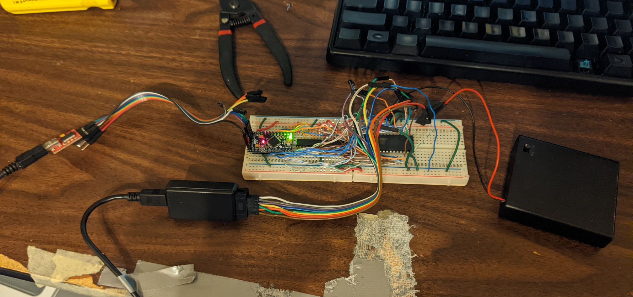
It didn’t take too long after the flash chips showed up that I decided to put together the programmer. I got out my very old wire stripper and some CAT5 cable from Toorcamp’s telephone network. I made wire after wire for each connection needed by the diagram. I tried to make them perfect like Ben Eater, but of course that went right out the window. So when I hooked it up, I was very nervous, worried about shorts and of course destroying the expensive and not very easy to find flash chips ($63.05 to replace all 10). Using my multimeter I checked over and over again making sure I wasn’t making any mistakes.
I used batteries instead of piggy backing on the USB power from the computer because I didn’t want the almost inevitable short to take out my computer. By only connecting data lines between my laptop and breadboard I could be fairly certain that I was not risking thousands of dollars on an experiment. This meant that my whole setup was powered by 4 rechargable AA batteries. It also meant that when the batteries ran low, my project was over for a while. I could have used batteries from my other devices, but I didn’t.
It was when I powered up the batteries that I started to worry. The voltage didn’t seem right, it was low. I unhooked the FTDI serial. I knew that it was just data lines but you always worry that the computer is somehow going to get a deadly voltage. The issue remained but got better. It should either go away or remain. Why would it get better? I tried removing the flash chip, the arduino pro mini, and each time it got better but not great. This is a learning moment. If it gets better but not as much as when you unplug the batteries and check the voltage, that means that something is wrong. It’s not the end of your project if you can’t fix it, though.
I noticed that I hooked up the arduino incorrectly. RAW is intended to receive unregulated power. If you have regulated power, that’s fine to use on VCC. So I fixed that. But the problem remained.
Eventually I decided it would make sense to turn the power off and check resistance and continuity. The most basic checks rapidly tell other people with some skill at repair what is wrong with a piece of hardware. Why wouldn’t it work for me? Well, it turns out that the basic checks failed. Rapidly. The flash chip had high resistance between power and power, ground and ground. For those who don’t understand electronics, any resistance between A and A is a big deal. Especially when a lot of voltage or amperage is supposed to flow, resistance is bad. So did the breadboard have a problem with the flash chip? I checked. Yeah that’s what it seemed to be. So I swapped out the wires and checked. It seemed better. But not exactly. After trial and error for a long time, I finally realize that I’m favoring checking a certain ground and power because it’s exposed. Why don’t I check the breadboard itself? The very first check of the breadboard turned up the problem: wiring from one side of the breadboard to the other was broken. All of the power rails and ground rails had a bunch of resistance between them. A wire connected ground one one side to ground on the other side. The project uses two breadboards, so the two breadboards are connected with wires. Those wires were not connected. Why? The breadboard itself wasn’t making a good connection to the wires. After picking a different hole, the problem went away – for the most part.
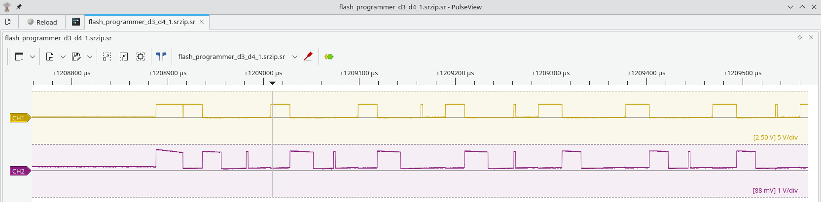
That’s right, it still wouldn’t flash my chips. So I brought out the first big gun: oscilloscope. If you have analog issues, I feel bad for you son, I got 99 problems but a _____ ain’t one. My cheap Hantek 6022BE is supported by Sigrok and Pulseview and is an excellent piece of hardware for getting captures of data, decoding on the fly, and indeed, all sorts of amazing mischief. It has 2 channels and supports pretty low voltages but has a 10x mode when you need extra. Hooking it up, I had lots of trouble figuring stuff out. March 3rd I spent 6:53 - 08:45 working with the oscilloscope. I got good captures and decided that the problem was probably visible in the logic analyzer.
I bought a logic analyzer from a legend of hardware hacking and hardware teaching, Joe Fitz as part of his side channel course many years ago. I’ve used it with the FitzSPA and a few other projects, but it fits this one pretty well. It looks quite similar to this one that is for sale on eBay for $9.89.
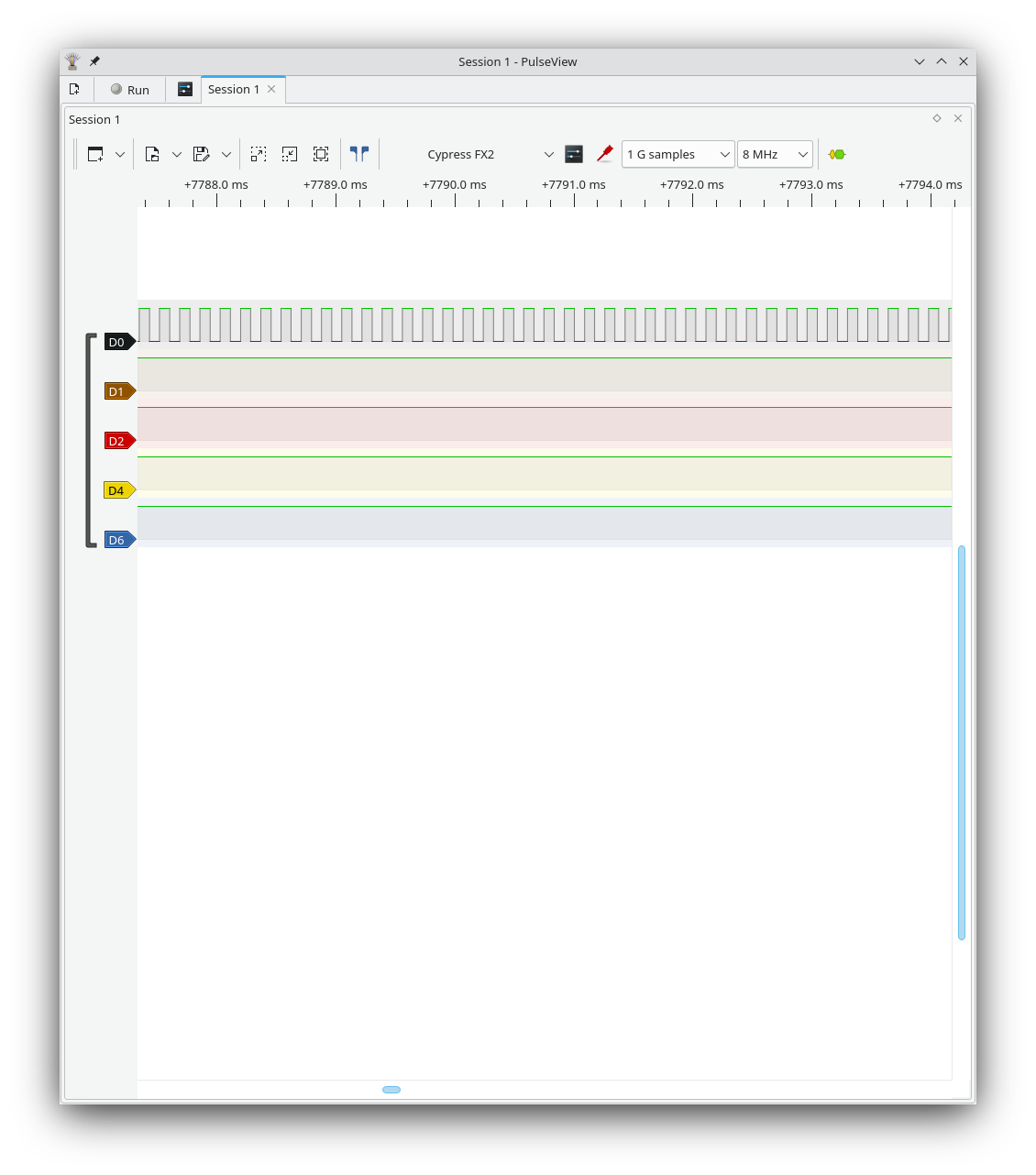
On March 5th I hooked up the logic analyzer rather haphazardly and tweeted an image of what I saw. It didn’t look right.
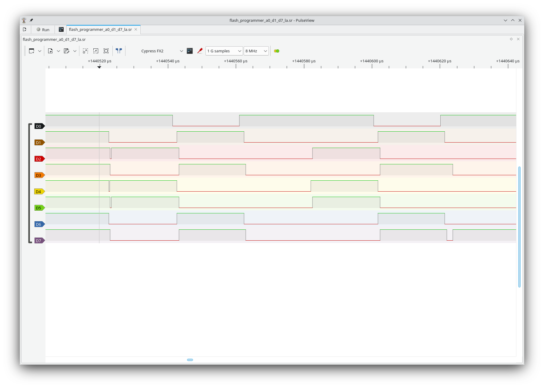
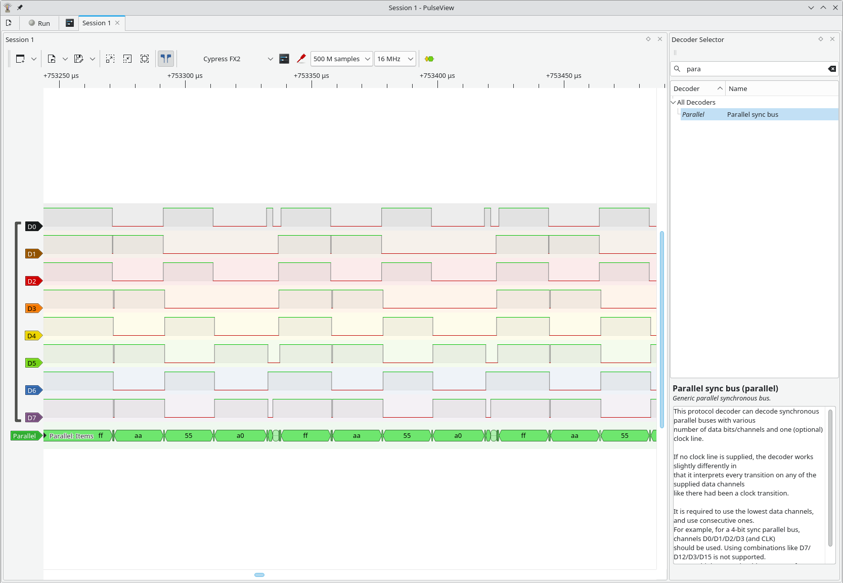
On March 21st, I spent the time to hook up D0-D7 correctly and used the parallel decoder. The parallel decoder showed that I had gotten D0-D7 hooked up correctly and was sending the right data during the write.
On March 24th, I hooked up d0 to output enable on the chip and did a read. That first read showed AAAAAAAAAAAAAAAAAAAAAAAAAAAAAAAA, which is what I had written on March 21st. Not having time to actually finish my work on March 21st, I didn’t have a chance to read. So the project was mostly complete then. I manually cut up my NES rom and modified my python script to support files 32kB in size. I ran a write and it failed 2kB before the end. I fixed my code and it worked. After checking the result, I was very satisfied. Somewhere along the way the flash programmer started working.
So what have I learned?
- Breadboards
Designed for prototyping and rapid iteration. - Circuit boards
Designed for reliable connections and to avoid the labor of making a hundred wires. - Resistance
A major issue in any electronics project. - Big Gun #1: Oscilloscope
A tool that can figure out simple problems with analog signals. - Big Gun #2: Logic Analyzer
A tool that can figure out very complex problems with digital signals.
This is a big win in my book having finally solved a pretty major electronics issue and getting a fairly complex piece of hardware working. The next step is to buy 5-10 boards and program the ATTiny chips with the proprietary algorithm. When the boards arrive and I solder the sockets onto them, we may see one of my ROMs written in 2017 run on an original NES. That will give me motivation to make games and improve my skills. A few of the important ROMs I want to play on my NES: the latest TetrisGYM, a modified version of NES Tetris where with level 20 colors on level 19, a modified version of TetrisGYM with level 18 speed on level 19-28, a modified version of NES Tetris with all speeds half as fast, and a modified version of TetrisGYM that has an option for an improved SPS.
Good luck on all your projects, Tetris or otherwise.
Javantea out.
Permalink-
Leave a Reply


Comments: 0
Leave a reply »